This post is going to explain how to use the ADS1015 Analog to Digital converter with Android Things. The board can convert analog sensor signals to digital input for the android things board, as well as acting as a programmable gain amplifier up to 16x. It has 12-bit precision at 3300 samples/second over I2C.
What are we going to do:
– Understand what the ADS1015 can do
– Show the library that abstracts away the I2C complexity
– Use the ADS1015 library demo to show possibilities
Lets .. get .. started
Always remember to refer to the datasheet (ADS1015 sheet found here) when you don’t understand something about a new peripheral.
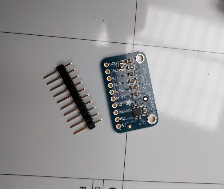
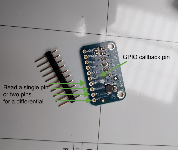
The ADS1015 has multiple ways it can be used, it has four input pins to read peripheral sensors. You can attach four separate analog sensors and read all four of them individually over I2C or you can attach two sensors with +,- and measure the differential between the two pins. There is also a comparator setting, meaning you can set a threshold value and when a single or pair of differential pins go above this value you get a callback on an alert pin.
A great use of this ADC is for converting analogue load cell readings to digital values for reading in AndroidThings. (An example can be seen here).
This interface includes all of the above features. You can read a single or pair of pins with the read(Channel) method, or you can set a threshold and wait for a callback with the startComparator method.
	interface Ads1015 {
		int read(Channel channel);

	    void startComparator(Channel channel, int thresholdInMv, ComparatorCallback callback);

	    void close();
	}

    enum Channel {
        ZERO(ADS1015_REG_CONFIG_MUX_SINGLE_0),
        ONE(ADS1015_REG_CONFIG_MUX_SINGLE_1),
        TWO(ADS1015_REG_CONFIG_MUX_SINGLE_2),
        THREE(ADS1015_REG_CONFIG_MUX_SINGLE_3),
        ZERO_AND_ONE(ADS1015_REG_CONFIG_MUX_DIFF_0_1),
        ZERO_AND_THREE(ADS1015_REG_CONFIG_MUX_DIFF_0_3),
        ONE_AND_THREE(ADS1015_REG_CONFIG_MUX_DIFF_1_3),
        TWO_AND_THREE(ADS1015_REG_CONFIG_MUX_DIFF_2_3);

        final int value;

        Channel(int value) {
            this.value = value;
        }
    }
The Ads1015 is like any other AndroidThings peripheral as it uses I2C for its communication. Therefore there is also a close() method that you should call when you have finished with the peripheral (usually in onDestroy).
This interface is available as an AndroidThings driver library. You can use it by adding it to your app like the below:
dependencies {
    compile 'com.blundell:driver-ads1015:<latest-version>'
}
First you need to create the factory. This is how you instantiate a new Ads1015. Once you have the factory you can decide if you are going to read pins or do a comparison. When you do a comparison you would wire up the alert pin, if you don’t need to do compare then you can use the simpler factory method like below:
// in onCreate
Ads1015.Factory factory = new Ads1015.Factory();
ads1015 = factory.newAds1015("I2C1", 0x48, Ads1015.Gain.TWO_THIRDS);

// when you want to read
int valueInMv = ads1015.read(Ads1015.Channel.ONE)
Log.d("TUT", "Read value " + valueInMv);;

// in onDestroy
ads1015.close();
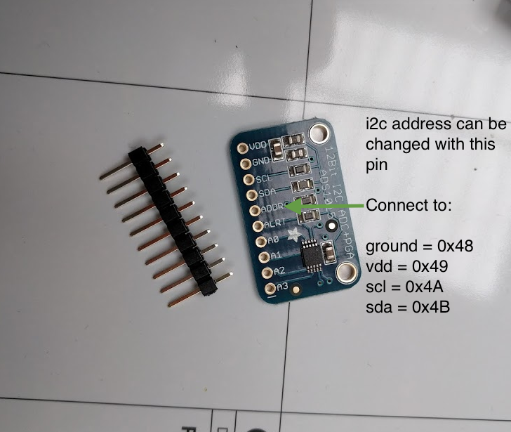
The i2c address is configurable, you have to wire the address pin to one of four other pins to change the address. This actually means you could measure 16 sensors at the same time (4 single read pins X 4 ads1015 boards). In the code above we use 0x48.
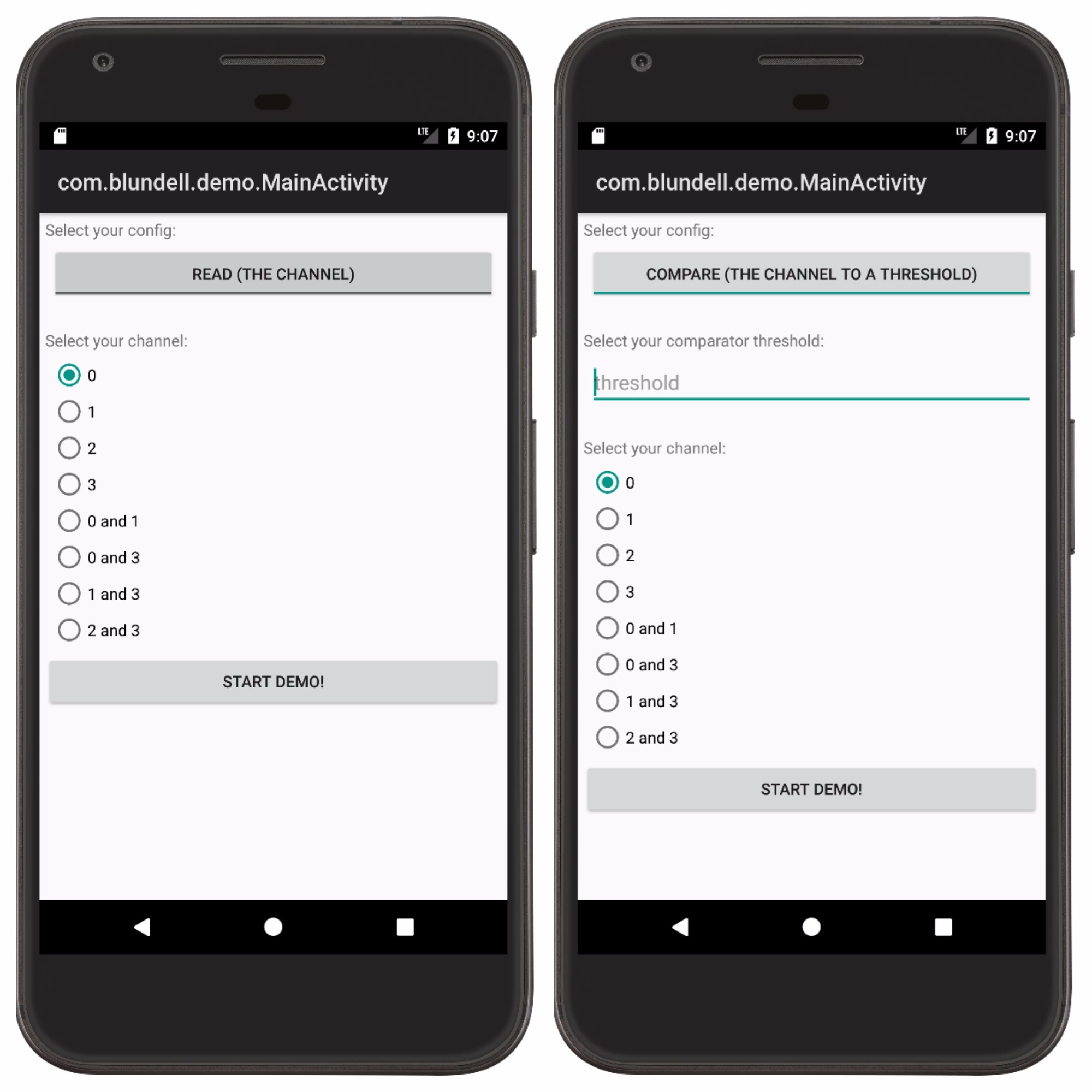
The code is available here ttps://github.com/blundell/ads1015 the library also has a demo module that you can run if your AndroidThings device has a display https://github.com/blundell/ads1015/tree/master/demo It will allow you to configure all the different settings for testing.
Thats it! This library abstracts the details of the Ads1015 I2C communication away for you. If you are interested in diving deeper into how this works I would recommend looking at the source code here.
Any questions just ask.